Draft Tube
- The draft tube is a pipe of gradually increasing area which connects the outlet of the runner to the tail race.
- It is used for discharging water from the exit of the turbine to the tail race.
- One end of the draft-tube is connected to the outlet of the runner while the other end is sub-merged below the level of water in the tail race.
- The draft-tube, in addition to serve a passage for water discharge, has the following two purposes also:
(a) It permits a negative head to be established at the outlet of the runner and thereby increase the net head on the turbine. The turbine may be placed above the tail race without any loss of net head and hence turbine may be inspected properly.
(b) It converts a large proportion of the kinetic energy (V22 / 2g) rejected at the outlet of the turbine into useful pressure energy. Without the draft tube, the kinetic energy rejected at the outlet of the turbine will go waste to the tail race.
CAVITATION IN REACTION TURBINE
- If the velocity of flow increases, as per Bernoulli’s equation the pressure will fall. If this pressure fall below vapour pressure, the liquid boils and a large number of small bubbles of vapour are formed. The bubbles collapse as water goes from low pressure region to high pressure region. This results in the formation of a cavity and the surrounding liquid rushes to fill it which results in rise of local pressure. It causes pitting on the metallic surface of runner blades or draft tube. Therefore, the material fails by fatigue aided perhaps by corrosion and causes lower efficiency of turbine.
- Cavitation depend on vapour pressure, absolute pressure, efficiency of draft tube etc.
Thoma’s Cavitation Factor
- Thoma’s cavitation factor is dimensionless number used to study the effect of caviation. For turbines, Thoma’s cavitation factor is given by
σ = (Ha – hs) – Hv/H
where, Ha = Atmospheric head, Hv = Vapour pressure head, hs = Suction head (at the outlet of reaction turbine) and H = Working head,
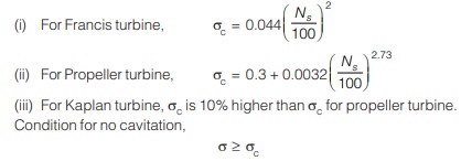
- Critical value of Thoma’s number (σc) depends upon Ns and is given by:
CLASSIFICATION OF ROTODYNAMICS PUMPS
Based on the direction of flow
- According to general direction flow of liquid within the passage of the rotating impeller, the rotodynamic pumps are classified as:
(a) Radial flow pump: The flow through the impeller is in radial direction i.e. in the direction right angle to the driving shaft of pump. It is the reverse of radially inward flow reaction turbine, i.e., francis turbine.
(b) Axial flow pump: The flow of liquid through the impeller is in axial direction only. These are designed to deliver more discharge for lesser heads.
(c) Mixed flow pump: It is the reverse modern francis turbine. It provides medium discharge for medium head.
Based on the type of casing
• Efficiency of turbine largely depends on the type of casing. It is designed in such a way to minimise the loss of kinetic head at the outlet of impeller through eddy formation and convert the kinetic head into pressure head before water leaves the casing and enters into the delivery pipe. On this basis, pump can be classified as: 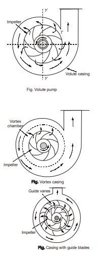
(a) Volute pump: In this, the impeller is surrounded by a spiral shaped casing which is known as volute casing. volute casing The shape of the casing is such that the cross sectional area of flow around the periphery of the impeller
gradually increases from tongue T towards the delivery pipe. This progressively expanding spiral casing decrease the velocity of water and correspondingly increases the pressure.
(b) Volute Pump with Vortex Chamber : A subsequent improvement over the simple volute casing was made by providing a circular chamber between the impeller and the volute chamber. This pump is known as Volute Pump with vor with vortex chamber tex chamber. tex chamber The liquid after leaving the impeller enters the vortex chamber with a whirling motion. No external work is done on the liquid as it passes through this chamber, so the motion is free vortex motion. For free vortex, velocity of whirl varies inversely as it passes through the vortex chamber. The reduction in velocity is accompanied by an increase in pressure. Hence efficiency of pump also increases.
(c) Diffuser pump or turbine pump: In this type of pump, there are guide blades surrounding the impeller the impeller the impeller mounted on a ring known as diffuser. Guide vanes are fixed in position. These guide vanes provide gradually enlarged passages for the liquid. It results in reduction in velocity of flow and consequently the pressure is built up. It is a very efficient pump.
<< Previous | Next >>
Must Read: What is Fluid Mechanics?
Dear Aspirants,
Your preparation for GATE, ESE, PSUs, and AE/JE is now smarter than ever — thanks to the MADE EASY YouTube channel.
This is not just a channel, but a complete strategy for success, where you get toppers strategies, PYQ–GTQ discussions, current affairs updates, and important job-related information, all delivered by the country’s best teachers and industry experts.
If you also want to stay one step ahead in the race to success, subscribe to MADE EASY on YouTube and stay connected with us on social media.
MADE EASY — where preparation happens with confidence.
MADE EASY is a well-organized institute, complete in all aspects, and provides quality guidance for both written and personality tests. MADE EASY has produced top-ranked students in ESE, GATE, and various public sector exams. The publishing team regularly writes exam-related blogs based on conversations with the faculty, helping students prepare effectively for their exams.
