Sludge Digestion Process
Stages of the Sludge Digestion Process
Three distinct stages have been found to occur in the biological action involved in the natural process of sludge digestion. These stages are:
(a) Acid Fermentation Stage or Acid Production Stage:
In this first stage of sludge digestion, the fresh sewage-sludge begins to be acted upon by anaerobic and facultative bacteria, called acid formers. These organisms solubilize the organic solids through hydrolysis. The soluble products are then fermented to volatile acids and organic alcohols of low molecular weight like propionic acids, acetic acids etc. Intensive acid production makes the sludge highly acidic, and lowers the pH value to less than 6. Highly putrefactive odours are evolved during this stage. BOD of the sludge increases to some extent, during this stage.
(b) Acid Regression Stage:
In this intermediate stage, the volatile organic acids and nitrogenous compounds of the first stage are attacked by the bacteria, so as to form acid carbonates and ammonia compounds. The decomposed sludge has a very offensive odour, and its pH value rises a little to about 6.8. The decomposed sludge, also, entraps the gases of decomposition, becomes foamy, and rises to the surface to form scum. This stage continues for a period of about 3 months or so. BOD of the sludge remains high even during this stage.
(c) Alkaline Fermentation Stage:
In this final stage of sludge digestion, more resistant materials like proteins and organic acids are attacked and broken up by anaerobic bacteria, called methane formers, into simple substances like ammonia, organic acids and gases. During this stage, the liquid separaes out from the solids, and the digested sludge is formed. This sludge is granular and stable and does not give offensive odours. This digested sludge is collected at the bottom of the digestion tank and is also called ripened sludge. Digested sludge is alkaline in nature. The pH value during this stage rises to a little above 7 (about 7.5 or so) in the alkaline range. Large volumes of methane gas along with small amount of carbon dioxide and nitrogen are evolved during this stage. This stage extends for a period of about one month or so. The BOD of the sludge also rapidly falls down during this stage.
DESIGN CONSIDERATION INVOLVED IN AN ACTIVATED SLUDGE PLANT
Sludge Volume Index (S.V.I):
It is used to indicate the physical state of the sludge produced in a biological aeration system. It represents the degree of concentration of the sludge in the system and hence decides the rate of (recycle of) sludge (QR) required to maintain the desired MLSS and F/M ratio in the aeration tank to achieve the desired purification. S.V.I. is defined as the volume occupied in ml by one gm of solids in the mixed liquor after settling for 30 minutes. Its unit is ml/gm. MLSS concentration in the aeration tank is controlled by sludge recirculation ratio and sludge settleability and thickening in secondary sedimentation tank. Sludge recirculation and settleability are determined by S.V.I. The relationship and settleability ratio (QR / Q) with Xt (MLSS in tank) and XR (MLSS in returned or wasted sludge) is given as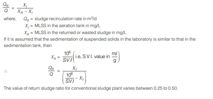
Experiment : The standard test, which is performed in the laboratory to compute SVI of an aeration system involves collection of one litre sample of mixed liquor from the aeration tank from near its discharge end in a graduated cylinder. The 1 litre sample of mixed liquor is allowed to settle for 30 minutes, and the settled sludge volume (Vob) in ml is recorded as to represent sludge volume. This volume (Vob) in ml per litre of mixed liquor will represent the quantity of sludge in the liquor ml/l. The above sample of mixed liquor, after remixing the settled solids, is further tested in the laboratory for MLSS by the standard procedure adopted for measuring the suspended solids in sewage. Let this concentration of suspended solids in the mixed liquor in mg/l by Xob.
Then SVI is given by the equation.
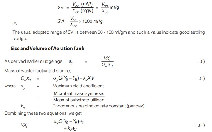
Using equation (iii), if value of MLSS concentration is assumed, then volume of tank V can be calculated.
It can be seen in equation (iii), that if value of Xt is kept high, then a low volume of reactor would be required.
However, there are some consideration that govern the upper limit of Xt which are as following:
- Initial and running cost of sludge recirculation system to maintain a high value of MLSS.
- Limitations of oxygen transfer equipment to supply oxygen at required rate in a small reactor volume.
- Increased solids loadings on secondary clarifier which may necessitate a larger surface area to meet limiting solid flux.
- Design criteria for tank and minimum H.R.T (t) for aeration tank for stable operation under hydraulic surges.
In extended aeration plants (other than oxidation ditches) and in complete mix plants, the tank shape may be kept circular or square when tank capacity is small, and rectangular with several side inlets and equal number of side outlets when the plant capacity is large.
In all other cases, aeration tanks are designed as long narrow channels. It is achieved by provision of round-the end baffles in small plants when only one or two tanks units are proposed and by constructing long and narrow rectangular tanks with common intermediate walls in large plants when several units are proposed.
For conventional plants, width and depth of aeration channel depend upon the type of aeration equipment used. The depth controls the aeration efficiency and usually ranges from 3 to 4.5 m. The higher value of depth of 4.5 m is found to be more economical for plants of more than 50 MLD capacity. Beyond 70 MLD, duplicate units are preferred. The width controls the mixing and is usually kept between 5 to 10 m. Width-depth ratio should be adjusted between 1.2 to 2.2. The length should not be less than 30 m and not ordinarily longer than 100 m in a single section length before doubling back. The horizontal velocity should be around 1.5 m/min. Excessive width may lead to settlement of solids in tank. Free board in tank is generally kept between 0.3 – 0.5 m.
While designing the aeration tanks, due consideration should also be given to need of emptying them for maintenance and repair of aeration equipment. Intermediate walls should be designed for empty conditions on
either side. The method of dewatering should be considered in design and provided during construction.
Advantage and Disadvantages of Activated Sludge Plant
The chief advantage of the activated sludge process is that it offers secondary treatment with minimum area requirements, and an effluent of high quality is obtained. The conventional process was somewhat difficult to operate and needed a lot of supervision. However, the modifications described earlier have made the process less difficult to operate than formerly, with the result that most secondary treatment plants being installed today are of these types.
Compared to the trickling filter plant, the capital cost of an activated sludge plant is less, but the operating cost is more mainly because of high power consumption for operating air compressors and the sludge circulation pumps. Generally, the power requirement in an activated sludge plant varies between 55 to 110 H.P. per million litres of sewage.
Loss of head through the plant is also quite less, and there is no fly or odour nuisance here, as there is in a trickling filter plant. However, if there is a sudden increase in the volume of sewage or if there is a sudden change in the character of sewage, adverse effects are produced on the working of the process, producing inferior effluent. Moreover, the quantity of sludge obtained is larger and needs suitable thickening and disposal.
<< Previous | Next >>
Must Read: What is Environmental Engineering?
Dear Aspirants,
Your preparation for GATE, ESE, PSUs, and AE/JE is now smarter than ever — thanks to the MADE EASY YouTube channel.
This is not just a channel, but a complete strategy for success, where you get toppers strategies, PYQ–GTQ discussions, current affairs updates, and important job-related information, all delivered by the country’s best teachers and industry experts.
If you also want to stay one step ahead in the race to success, subscribe to MADE EASY on YouTube and stay connected with us on social media.
MADE EASY — where preparation happens with confidence.
MADE EASY is a well-organized institute, complete in all aspects, and provides quality guidance for both written and personality tests. MADE EASY has produced top-ranked students in ESE, GATE, and various public sector exams. The publishing team regularly writes exam-related blogs based on conversations with the faculty, helping students prepare effectively for their exams.
