Welded Joints
- In welded connections, the two structural members are joined by a weld.
- It is the compactness and greater rigidity of the welded joints that offer design assumptions to be realized more precisely in practice.
Advantages of welded joints over other joints:
(a) Welded joints offer more efficient use of materials and it is due to welding only that we are able to have one piece construction.
(b) Welding helps in speeding up the erection and construction process thereby compressing the production schedules.
(c) Welding offers light weight construction and thus cuts costs of construction. Connecting steel plates are reduced or eliminated thereby reducing the self-weight of the structure.
(d) In welding, no deductions for holes are made and thus whole of the gross section is effective in carrying the load.
(e) Welded joints perform better in case of fatigue loads, impact loads and vibrations.
(f) Welding offers complete freedom to architects and the engineers for their designs.
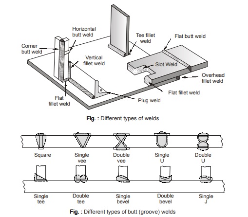
TYPES OF WELDED JOINTS
- Depending on the type of weld, welded joints can be classified as:
(a) Fillet weld
(b) Butt or groove weld
(c) Plug weld
(d) Slot weld
(e) Spot weld - Depending on position, welded joints can be classified as:
(a) Flat weld
(b) Horizontal weld
(c) Vertical weld
(d) Overhead weld - Depending on the type of joint, welded joints can be classified as:
(a) Butt or groove weld
(b) Lap weld
(c) Tee weld
(d) Corner weld
All the above types of welds are shown in figure below:
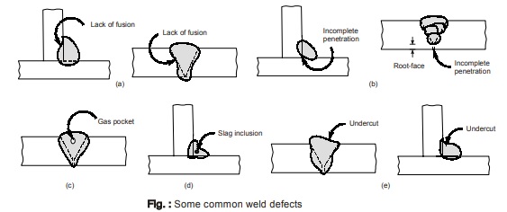
Groove/butt welds require edge preparation and thus are costly. Single V, U, J etc. butt welds are cheaper to form but require double the weld metal than double grooved joints.
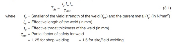
WELD DEFECTS
(a) Incomplete fusion: It is the failure of the base (or parent) metal to get completely fused with the weld metal. This defect occurs because of rapid welding and also because of foreign materials on the surfaces to be welded.
(b) Incomplete penetration: It is the failure of the weld metal to penetrate completely the depth of the joint.
This defect normally occurs with single V and bevel joints and also because of large sized electrodes.
(c) Porosity: It occurs due to gas or void packets entrapped in the weld while cooling. This results in stress concentration and reduced ductility of the metal. Normally porosity is not a problem because such voids are spherical in shape which allows a smooth flow of stress around the void without any significant loss in strength.
(d) Slag inclusion: These are metal oxides and other solid compounds which are often found as elongated or globular inclusions that are being lighter than the molten material and these float and rise to the weld surface from where these are removed after cooling of the weld. But excessive rapid cooling of the weld may cause them to get entrapped in the weld which poses a problem especially in vertical and overhead welding.
(e) Cracks: Cracks can be hot or cold. Hot cracks occur due to the presence of sulphur, carbon, silicon and hydrogen in the weld metal. Phosphorous and hydrogen trapped in the hollow spaces of the metal structure give rise to the formation of cold cracks. Preheating of the metals to be welded eliminates the cracks formation.
(f) Undercutting: It is the local decrease in the thickness of the parent metal at the weld toe. This occurs due to excessive current or very long arc. An undercut results in the loss of gross section and in fact acts like a notch.
BUTT (OR GROOVE) WELDS
- A square butt weld is provided for sections up to 8 mm thickness only.
- For sections with thickness greater than 8 mm, a single U, V or double U, V etc. butt welds are provided.
- Butt weld is mainly designed for direct compression or tension and occasionally for shear also. Butt weld is mainly designed for direct compression or tension and occasionally for shear also.
- The advantage with butt weld is that it involves no change in section at the location of joint and is thus the most preferred type of weld for transmitting alternating stresses.
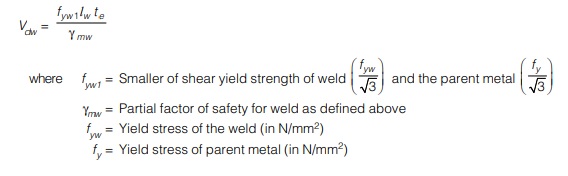
Design Strength of Butt Weld
- The design strength of butt weld in tension or compression is tension or compression governed by the smaller of the yield strength of weld or the parent metal and is given by
- The design strength of butt weld in shear is also governed by yield and is given by,
FILLET WELD
- This weld is required where members overlap each other or the connecting members are in different planes. In such cases butt weld cannot be provided.
- Fillet weld is predominantly subjected to shear stresses.
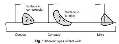
- Fillet weld can either be convex or concave as per requirement as shown in figure above.
- From appearance point of view, concave fillet weld appears to be larger in length than convex fillet weld but actually concave fillet weld has less penetration and smaller throat thickness. Thus convex fillet weld is stronger even with less deposited metal. Convex fillet weld shrinks on cooling and thus stresses induced on outer face are compression.
- When concave fillet weld cools, the outer surface is stressed in tension. Thus, cracks get developed in concave fillet welds on cooling.
- Concave fillet welds are made in more than one pass, the first pass being slightly convex and subsequent passes are built up to form concave fillet weld. Concave fillet welds are more suitable under repetitive type of stresses.
Design Strength of Fillet Weld
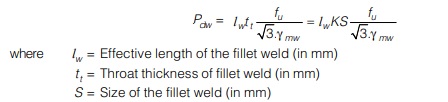
- The design stress in a fillet weld is given by,
fwd = fwn / γmwwhere fwn = Nominal strength of fillet weld = fu / √3 - The design strength of a fillet weld is a function of throat area and is given by,
Procedure for the Design of Fillet Weld
A fillet weld may be subjected to any general type of stress i.e. axial/direct stress (tensile or compressive), flexural stress (tension or compression) and shear stresses but the design of fillet weld is governed by shear stresses since a fillet weld always gets fail in shear.
Step-1. The size of the fillet weld (S) is assumed to be forehand based on the thickness of the members
to be jointed.
Step-2. An equal legged fillet weld gets fail at an angle of 45° through the throat. The strength of the weld is computed from Eq. (3.5). Eq. (3.5).
Step-3. Force to be transmitted by the joint is either known or is estimated.
Step-4. The effective length of the weld is worked out by dividing the factored force by the strength of the weld per unit (usually mm) length. The resulting weld length is adjusted either by providing longitudinal fillet welds (parallel to the force) or transverse fillet weld (normal to the force) in combination with longitudinal fillet weld. It is assumed that both the welds are stressed equally. If required length of the weld exceeds 150 tt then design capacity of the weld is reduced by the factor βlw as defined by Eq. (3.3).
Step-5. If only longitudinal fillet weld is provided then length of each longitudinal fillet weld must be more than the perpendicular distance between them.
Step-6. At each end of the longitudinal fillet weld, end returns of length 2S are provided.
FILLET WELD FOR TRUSS MEMBERS
Truss members are generally composed of single-angle or double-angle sections. The following points should be kept in mind while designing the weld.
- A longitudinal fillet weld shall never be placed on one side only as there will be possibility of rotation.
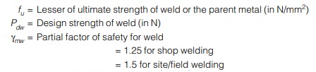
- The weld length calculated is provided as longitudinal fillet welds either on the two sides parallel to the axis of load or on there sides as shown in figure.
- The centre of gravity of the weld should coincide with the centroid of the section used as truss member. If the member is symmetrical, the welds are placed symmetrically but if the member is unsymmetrical, the lengths of the longitudinal welds are so designed so as to satisfy the above condition.
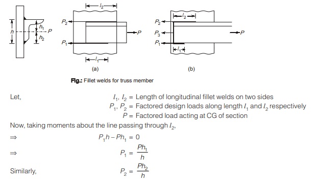
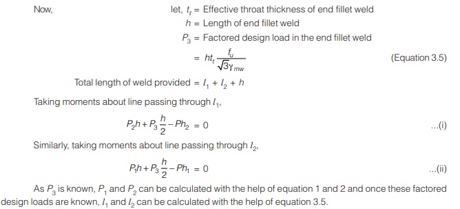
- Once the design factored loads P1 and P2 are obtained, the fillet weld can be designed as per equation 3.5 as discussed earlier.
- However, when the weld length to be provided cannot be accommodated over the two parallel sides, end weld connecting the two parallel sides may be provided as shown in figure. This arrangement also proves to be economical, as it reduces the size of gusset plate to be provided.
<< Previous | Next >>
Must Read: What is Power Electronics?
Dear Aspirants,
Your preparation for GATE, ESE, PSUs, and AE/JE is now smarter than ever — thanks to the MADE EASY YouTube channel.
This is not just a channel, but a complete strategy for success, where you get toppers strategies, PYQ–GTQ discussions, current affairs updates, and important job-related information, all delivered by the country’s best teachers and industry experts.
If you also want to stay one step ahead in the race to success, subscribe to MADE EASY on YouTube and stay connected with us on social media.
MADE EASY — where preparation happens with confidence.
MADE EASY is a well-organized institute, complete in all aspects, and provides quality guidance for both written and personality tests. MADE EASY has produced top-ranked students in ESE, GATE, and various public sector exams. The publishing team regularly writes exam-related blogs based on conversations with the faculty, helping students prepare effectively for their exams.
