Types of Failure in Tension Members
Types of Failure
(a) Yielding of gross section (Tdg): In this type of failure wherein the yielding of the gross section occurs there a significant amount of deformation occurs before the material actually gets fractured. This significant amount of deformation makes the structure unserviceable.
(b) Rupture of net section (or fracture) (Tdn): When the net section of the member reaches the ultimate stress, then rupture (or fracture) of member takes place.
(c) Block shear failure (Tdb): Here a segment of the block of the material at the corner of the connection shears out due to use of high bearing strength of steel and high strength of bolts resulting in smaller connection length.
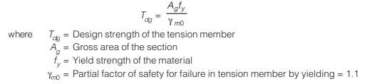
DESIGN STRENGTH OF A TENSION MEMBER
The design strength of a tension member is based on two limit states viz.:
(a) Limit state based on yield strength of the member due to its large elongation.
(b) Limit state based on ultimate strength of the member. This limit state is particularly crucial where the section of the tension member gets reduced due to the presence of bolts holes etc.
A tension member with bolt holes at the ends for connection purpose etc., even if subjected to tensile stresses in excess of yield stress to as high as ultimate stress, the member may not elongate excessively. because of the presence of so called non active metal behind the bolt holes in the direction of tensile force. Just at the point of fracture (i.e. breaking), the metal tends to narrow out at that point where the fracture occurs but the additional metal present behind the bolt hole restricts this contraction of the strained metal thereby increasing the ultimate strength. Thus fracture strength at the net section passing through the bolt holes is considered as another limit state.
The design strength of a tension member is the minimum of the following:
(a) Design strength due to yielding of the gross section (Tdg)
(b) Rupture strength of critical section (Tdn)
(c) Block shear strength (Tdb)
Limit state – 1: Design Strength Due to Yielding of the Gross Section (Tdg)
- This limit state tries to prevent the excessive elongation of the tension member.
- In order to prevent the attainment of this limit state, the stress on the gross section must be less
than the yield stress of the material (fy). - Though yield stress may reach at the net section prior to the gross section but this length of connection is too small as compared to overall length of the tension member and thus elongation in the unreduced sectional part will be more than the elongation in the holes region.
NOTE: It is the larger elongation and not the attainment of yield first that is considered as a limit state. - Thus to prevent the excessive elongation in the tension member, the stress on the gross section must be less than the yield stress i.e.
T/Ag < fy
T < fyAg
Limit State -2: Design Strength Due to Rupture of Net Section
- Presence of holes in the section cause stress redistribution around the holes and makes the stress near to the holes to be larger than the average stress at the bolt hole (=P/A) as shown in figure below.
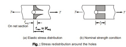
- This stress variation across the net section will become uniform as the stress approaches the yield stress thereby approaching the plastic state.
NOTE: The ratio of maximum elastic stress (fmax) to the mean stress (favg) is often known as stress concentration factor concentration factor - The stress in the fibers near to the hole reaches the yield stress (fy) and remains constant as the load is increased but the stress in the sectional regions away from the hole gradually increases till they reach the yield stress (fy).
- Because of the ductility of steel, initially yielded zone undergoes more deformation till the member fractures through the holes. At this stage, the stress in the entire net section reaches the ultimate stress (fu).
- In order to prevent the net section fracture of a tension member,
T < Anfu - The design strength due to rupture of net section is given by,
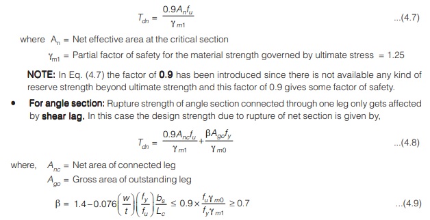
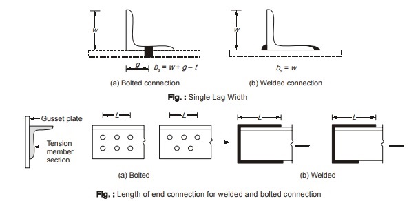
w = Width of outstanding leg of angle section.
bs = Shear lag width as shown in figure below.
t = Thickness of the leg.
Lc = Length of the end connection i.e. distance of the outermost bolt of the end joint measured in the loading direction or the length of the weld in the direction of load.
For preliminary design purpose, IS code recommends the following expression:
Tdn = αAnfu / γm1
where,
α = 0.6 when number of bolts ≤ 2
= 0.7 when number of bolts = 3
= 0.8 when number of bolts ≥ 4
= 0.8 for welds
- For other sections: The rupture strength for other sections like the double angle, T-section, I-section, channel etc. may be determined by the same equations as for single angle section with bs taken from farthest edge of the outstanding leg to the nearest bolt line or weld line in the connected leg.
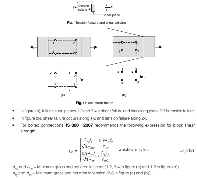
Limit State-3: Block Shear Strength 
- At the connected end of a tension member, failure may occur along a path which involves shear along one plane and tension on the orthogonal plane along the fastener. This type of failure is referred to as block failure.
- When applied tensile load is increased, weaker plane approaches its fracture strength. However as this plane is restrained by the stronger plane, failure does not takes place. The load can still be increased till the fracture strength of the stronger plane is reached. During this duration, the weaker plane is yielding. Thus we can conclude that the total strength equals the fracture strength of the stronger plane plus the yield strength of the weaker plane.
- Consider the member shown in figure below. The member has a large shear area and a small tensile area. Thus in this case, primary resistance to block shear failure will be shearing and not tensile.
Therefore, it is logical to assume that when shear fracture occurs on this large shear resisting area, the smaller tensile area has yielded. - For the welded connection shown below, the member has a large tensile area and a smaller shear area. Thus in this case the primary resisting force against block shear will be tensile and not shearing. Therefore in this case it is logical to assume that when tensile fracture occurs on the larger tensile resisting area, the smaller shear area has yielded.
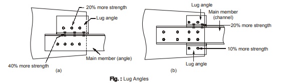
LUG ANGLES
- For a heavily loaded tension member, the length of the connection comes out to be too large to be accommodated on a gusset plate.
- This length of connection can be reduced by using lug angles as shown in figure below.
- Use of lug angles saves the cost of gusset plate but this saving is offset by additional fasteners and angles required.
Cl. 10.12 of IS 800 : 2007 specifies certain requirements for lug angles which are as given below:
(a) The effective connection of the lug angle shall be as far as possible, terminate at the end of the member.
(b) The connection of the lug angle to the main member shall preferably start in advance of the member to the gusset plate.
(c) For connecting lug angle to the gusset, a minimum of two bolts or rivets or equivalent weld length should be used.
(d) In case, the main member is an angle then:
(i) The whole area of the main member shall be taken as effective instead of net effective section (i.e. effect of shear lag is ignored). The whole area of member is calculated by deducting the area of bolt holes from the gross cross-sectional area.
(ii) The strength of lug angles and fasteners connecting lug angle to gusset plate must be at least 20% more than the force in the outstanding leg.
(iii) The strength of fastener connecting lug angle and main member shall be at least 40% more than the force carried by the outstanding leg.
(e) In case the main member is a channel section then,
(i) As far as possible, the channel should be symmetric.
(ii) The strength of fasteners connecting lug angle to the gusset should be at least 10% more than the force in the outstanding leg.
(iii) The strength of fasteners connecting lug angle to the main member should be at least 20% more than the force in the outstanding leg.
<< Previous | Next >>
Must Read: What is Power Electronics?
Dear Aspirants,
Your preparation for GATE, ESE, PSUs, and AE/JE is now smarter than ever — thanks to the MADE EASY YouTube channel.
This is not just a channel, but a complete strategy for success, where you get toppers strategies, PYQ–GTQ discussions, current affairs updates, and important job-related information, all delivered by the country’s best teachers and industry experts.
If you also want to stay one step ahead in the race to success, subscribe to MADE EASY on YouTube and stay connected with us on social media.
MADE EASY — where preparation happens with confidence.
MADE EASY is a well-organized institute, complete in all aspects, and provides quality guidance for both written and personality tests. MADE EASY has produced top-ranked students in ESE, GATE, and various public sector exams. The publishing team regularly writes exam-related blogs based on conversations with the faculty, helping students prepare effectively for their exams.
