Tensile Strength of Plate
- If tensile load acting on the plate exceeds tensile strength of the plate then failure of joint in the form of tension failure or rupture takes place.
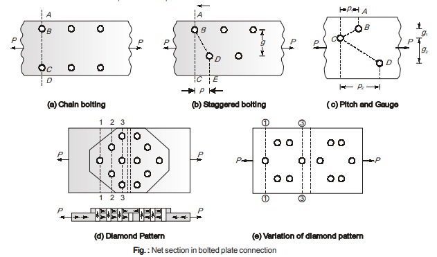
NOTE: For main plate critical section is at (1)-(1), while for cover plates critical section is at (3)-(3).
- Diamond riveting (d) is better than other (a, b, c) arrangements as only one rivet hole is deducted at section (1)-(1) but three holes are deducted at (3)-(3) which makes cover plate weak.
- To eliminate above problem a variation of diamond arrangement may be provided as shown in (e). In this arrangement both main plate and cover plate are relatively strong than other arrangements.
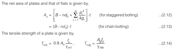
Hence it is best arrangement. - The net area of plates and that of flats is given by
fu = Ultimate stress of the material (in N/mm2)
An = Effective area of the plate (in mm2)
γm1 = Partial factor of safety for material strength governed by ultimate strength = 1.25
γm0 = Partial factor of safety for material strength governed by yielding strength = 1.1
Tensile strength of plate is taken as min. , {Tnd1 , Tnd2}
STRENGTH AND EFFICIENCY OF A BOLTED JOINT
- The strength of a joint is the minimum of strength of bolts in shear and bearing and strength of main connected member at the net section.
- The efficiency of a bolted joint (η) is defined as the ratio of strength of a joint to the strength of the main connected member i.e.
η = Strength of bolted joint / Strength of solid plate x 100
PRYING ACTION
It is assumed that high strength bolts are non-deforming and are subjected to tensile forces when tightened. The tension force is close to yield strength of the bolts. As shown below in figure (a), a T hanger is subjected to a concentric tensile load T1. Thus for a tensile load that is applied to sung type of bolt (i.e. bolts with no initial tension), the tensile force in the bolt will be equal to the applied tensile load.
In case of high strength bolts that are fully tensioned, pre-stress in the joints get introduced (tensile force in the bolts due to full tightening) and the connected member plates get squeezed. The bolts are under initial tension Ti . For static equilibrium, the connected parts are subjected to compression Ci and are thus prestressed as shown below in figure (b). Due to prestressing of the plates, the thickness of the plates gets reduced which consequently reduces the tension in the connectors and subsequently the compressive stress in the plate. This increases the plate thickness. The whole sole effect is that neither the plate thickness nor the connector tension is changed. Thus the connection subjected to tensile load T1 equals the total tension 2Ti in the connectors. Thus the tensile force in high strength bolts should be computed without considering any initial tension. Application of any additional tensile load to the connection cannot exert any additional load on the bolts unless the connected members are pulled apart thereby creating additional strain in the bolts. But this increase in bolt strain is accompanied by expansion of plates. In fact the increase in bolt tension is very small due to the additional load which is shared between the plate and the connectors roughly in proportion to their stiffness and the plates being stiffer take the most of load.
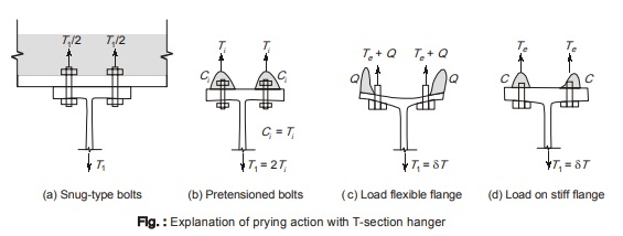
The stiffness (or flexibility) of the T hanger flange plays a prominent role in the determination of resultant tension in bolts. In case of very flexible flange, if load is increased, the contact stress in the vicinity of bolts decrease and will reduce to zero as the flange separates from the support. Moreover, since the flange will bend, the outer portion of the flange will be forced against the support and develop contact stresses in different locations as shown above in figure (c). This is called as prying stress. In most of the connections subjected to tension in general, due to the flexibility of connected parts, can lead to deformations that increase the tension applied to bolts. This additional tension force is called as prying force. For static equilibrium, the total force in the bolts must be equal to the applied force plus the prying forces. Thus the useful capacity of the bolt gets decreased by prying force. The maximum value of prying force will be reached only when the corners of the hanger flange remain in contact with the other connected part. Depending on their relative stiffness of the connected part and the bolt, the prying action may be negligible or it may be quite significant in proportion to total tension in the bolts.
On the other hand, for very stiff flange, the picture is quite different. Its flexural deformations will be negligible relative to the bolt elongation. Bending will cause the compressed zones of the connected parts to loose their symmetry but this compression remains localized in their bolt regions as shown above in figure (d). This system is identical to an indeterminate condition. At this stage a very little pressure gets exerted by the support on the rest of the flange. With further increase of load, the contact stress will reduce to zero and the system becomes statically determinate and no additional tension will be developed on the fasteners.
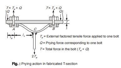
The hanger connection as shown above in figure (c) and figure below is an instance of connection subjected to prying action. In this type of connection, bending due to the prying action will usually control the design. The additional force Q in the bolts due to prying action should be added to tensile force Te resulting directly from the applied forces.
It is quite cumbersome to determine the exact magnitude of prying force, and thus approximate formulae are developed.
In the figure shown flanges of the hanger are thick and stiff (or are stiffened). In this case the prying action will be negligible. Thus in order to prevent significant deformations in the hanger and other similar connections, the use of rigid flanges is recommended.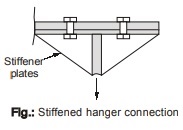
<< Previous | Next >>
Must Read: What is Power Electronics?
Dear Aspirants,
Your preparation for GATE, ESE, PSUs, and AE/JE is now smarter than ever — thanks to the MADE EASY YouTube channel.
This is not just a channel, but a complete strategy for success, where you get toppers strategies, PYQ–GTQ discussions, current affairs updates, and important job-related information, all delivered by the country’s best teachers and industry experts.
If you also want to stay one step ahead in the race to success, subscribe to MADE EASY on YouTube and stay connected with us on social media.
MADE EASY — where preparation happens with confidence.
MADE EASY is a well-organized institute, complete in all aspects, and provides quality guidance for both written and personality tests. MADE EASY has produced top-ranked students in ESE, GATE, and various public sector exams. The publishing team regularly writes exam-related blogs based on conversations with the faculty, helping students prepare effectively for their exams.
