Slab Base
- When column is subjected only to axial loads then column base plate can be designed by assuming a uniform base pressure distribution from below.
- For small loads, a steel plate shop welded to the column can be used to transmit the column load to the concrete pedestal as shown in figure below.
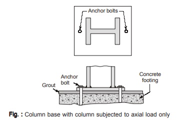
- For bolted construction, cleat angles are bolted to the base plate in shop and column is placed between them while erection. Such a base plate is called slab base and is considered to be a pin base.
- When column is subjected to bending moments along with axial load, angle sections are attached to the flanges of the column. These angles are anchored with the foundation bolts to the concrete pedestal as shown in figure below.
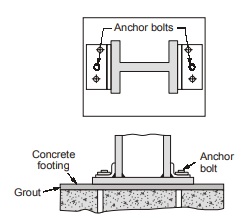
- Even if a column is subjected to direct axial load only, then also nominal angle sections are provided in order to keep the column at place and to resist tension during erection and connection. These angles may safely be omitted in case base plate is shop welded to the column.
- Depending on the values of axial load and bending moment coming over the column, it may be possible that whole of the column base is under compression or a part of the base is under compression and part under tension. Hold down bolts are provided to resist tension forces which also help in fixing the column to the base.
- The thickness of the base plate is designed from consideration of bending of the portion of base plate that extends beyond the column profile. In case where such projections are large, or the loads are very heavy, or the moments are large, there the thickness of the base plate may be reduced by the use of vertical stiffeners or plates as shown in figure of some typical welded column bases.
Design of Slab Base
- The projection of slab base beyond the column profile acts as cantilevers and thus maximum bending moment occurs at the edge of the column.
- The slab tends to bend simultaneously about the two principal axes of the slab and therefore the stresses induced in one direction are influenced by the stresses due to bending in other axis. A Poisson’s ratio of 0.3 is generally used to account for this effect.
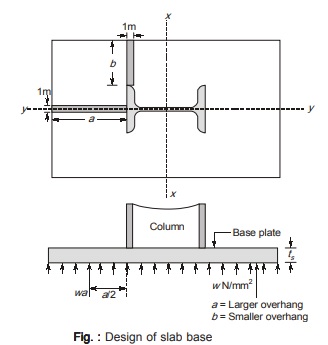
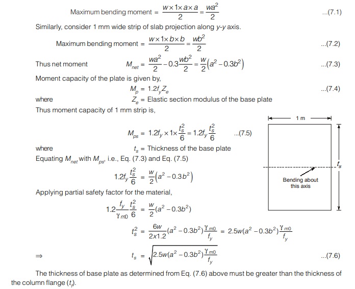
Consider 1 mm wide strip of slab projection along x-x axis.
Let w = Intensity of bearing pressure from concrete below the base plate
Procedure for the Design of Slab Base
Step-1 Assume a suitable grade of concrete (if not already mentioned) and compute bearing capacity of concrete as 0.45fck.
Step-2 The required area of the slab base is computed as,
A = Pu / 0.45fck
where A=Required area of the base plate in mm2
Pu=Factored load from column
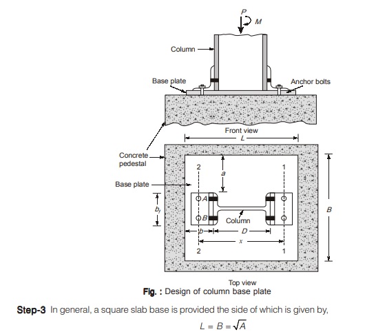
Another practice of column base design is that projections beyond the column profile i.e. a and b may be kept equal and the sides of the base plate is worked out as,
(D + 2b).(bf + 2a) = A
where, L = Length of the base plate in mm
B = Width of the base plate in mm
a = Larger projection of base plate beyond column in mm
b = Smaller projection of base plate beyond column in mm
D = Overall depth of the column section in mm
bf = Width of flange of column section in mm
Step-4 The intensity of the base pressure w from concrete pedestal is calculated as,
w = Pu / A1
where A1 = Area of base plate provided in mm2
w = Intensity of base pressure from concrete pedestal in N/mm2
Step-5 The minimum required thickness of the base plate (ts) is computed from Eq. (7.6) and it must not be less than thickness of the column flange (tf).
Step-6 Holding down bolts 2 or 4 in numbers of 20 mm diameter are generally provided.
Step-7 Welded Step-7 joint between the column and base plate is designed. If however, column and base have machined ends and perfect bearing is assumed then axial load is assumed to be transferred directly and welding is designed for moments only (if any)
<< Previous | Next >>
Must Read: What is Power Electronics?
Dear Aspirants,
Your preparation for GATE, ESE, PSUs, and AE/JE is now smarter than ever — thanks to the MADE EASY YouTube channel.
This is not just a channel, but a complete strategy for success, where you get toppers strategies, PYQ–GTQ discussions, current affairs updates, and important job-related information, all delivered by the country’s best teachers and industry experts.
If you also want to stay one step ahead in the race to success, subscribe to MADE EASY on YouTube and stay connected with us on social media.
MADE EASY — where preparation happens with confidence.
MADE EASY is a well-organized institute, complete in all aspects, and provides quality guidance for both written and personality tests. MADE EASY has produced top-ranked students in ESE, GATE, and various public sector exams. The publishing team regularly writes exam-related blogs based on conversations with the faculty, helping students prepare effectively for their exams.
