Shape Factor
- Shape factor gives an indication of the reserve capacity of a section from the onset of yielding at xtreme fibres upto full plastification.
- It is defined as the ratio of the plastic moment to the yield moment of the section.
- It is represented by ‘S’ and is a function of the cross-section shape.
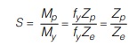
where Zp is the plastic section modulus as defined in section 12.4 and Ze is the elastic section modulus defined as the the first moment of area and is expressed as I / y where I is the second moment of area and y is the distance of extreme fibre from neutral axis, which is the centroidal axis in the elastic analysis.
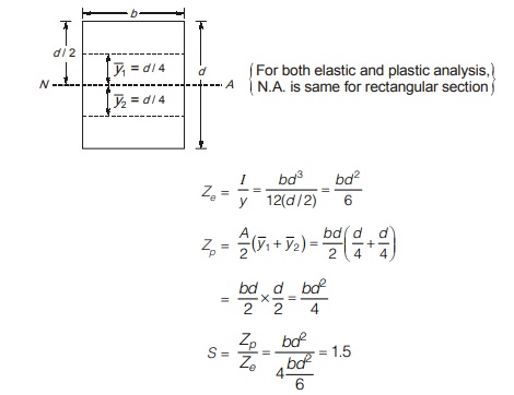
For example, consider a rectangular section of dimensions as shown. In this case, the centroidal and the equal area axis coincide. Elastic section modulus, Ze is given by
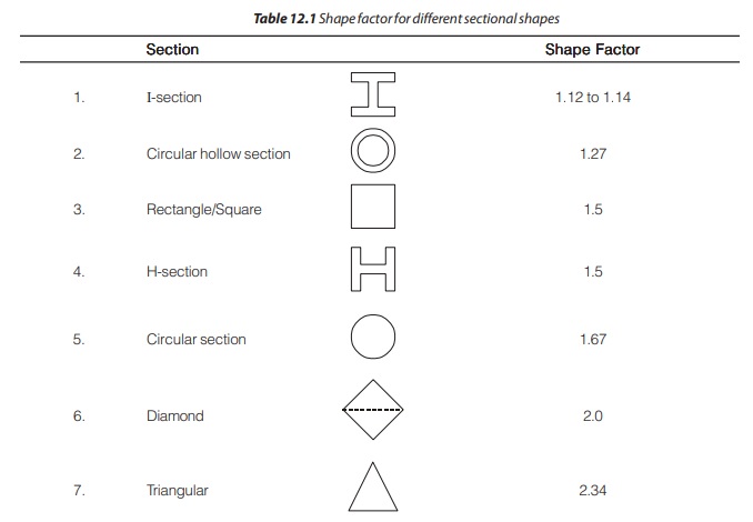
The shape factor for some of the other sections are given in table below.
LOAD FACTOR
It is defined as the ratio of the collapse load to the working load. It ensures that the structure will be safe under service condition.
Load factor, F = Wu / Ws
For a simple beam, the variation of the bending moment with the load is linear. Thus F can also be defined as
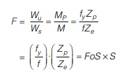
where FoS is the factor of safety, S is the shape factor.
Therefore the load factor may also be defined as the product of the factor of safety and shape factor.
PLASTIC HINGE
- Flexural members remain elastic until the moment reaches a value Mp, the maximum moment of resistance of a fully yielded cross section.
- Any additional moment will cause the beam to rotate with little increase of stress.
- This rotation occurs at a constant moment Mp. This zone acts as a hinge except with a constant restraining moment Mp.
- In reality hinges do not form but large changes in slope occurs over very small lengths of the member at the location of maximum moment.
- Strain hardening occurs at these hinges so that large deflections are accompanied by a little increase of loads. This plastic hinge is represented by a black dot.
- A structure can sustain the computed ultimate loads due to successive formation of plastic hinges at critical locations. The plastic hinges are formed first at the location of greatest deformation (i.e. curvature).
- Possible Places of Plastic Hinge formation in a Structure with Prismatic Members/material.
- Point of concentrated load
- At the ends of member meeting at a connection involving a change in geometry.
- Point of zero shear in structure subjected to uniformly distributed load.
- At the location of fixed ends.
HINGE LENGTH
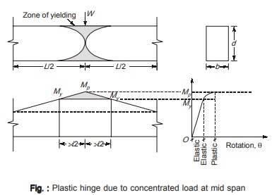
- As shown below in figure, the value of moment at sections adjacent to the yield zone for a certain length is more than the yield moment. This little length is called as hinge length.
- This hinge length depends on the loading type and the geometry of the cross section.
- For simplified analyses, this hinge length is neglected and plastic hinge is considered to be formed at particular points of zero length.
- But this hinge length cannot be neglected in calculation of deflections and the design of bracings as the length over which yielding extends is quite important.
Let there be a simply supported beam which is subjected to a gradually increasing concentrated load W at the mid span. A plastic hinge will form at the center of the beam as shown above in figure.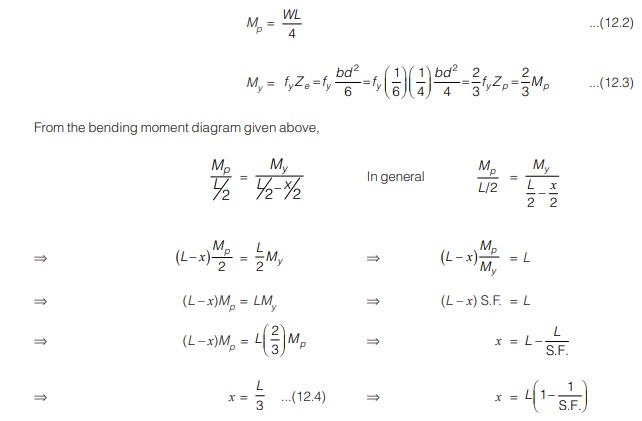
Thus length of plastic hinge in a beam subjected to concentrated load at mid span is L/3 where L is the span of the beam.
<< Previous | Next >>
Must Read: What is Power Electronics?
Dear Aspirants,
Your preparation for GATE, ESE, PSUs, and AE/JE is now smarter than ever — thanks to the MADE EASY YouTube channel.
This is not just a channel, but a complete strategy for success, where you get toppers strategies, PYQ–GTQ discussions, current affairs updates, and important job-related information, all delivered by the country’s best teachers and industry experts.
If you also want to stay one step ahead in the race to success, subscribe to MADE EASY on YouTube and stay connected with us on social media.
MADE EASY — where preparation happens with confidence.
MADE EASY is a well-organized institute, complete in all aspects, and provides quality guidance for both written and personality tests. MADE EASY has produced top-ranked students in ESE, GATE, and various public sector exams. The publishing team regularly writes exam-related blogs based on conversations with the faculty, helping students prepare effectively for their exams.
