Self Weight of a Plate Girder
The self weight of a plate girder can be estimated from the following empirical relation:
w = W/200 kN/m
where w = Factored self-weight of the plate girder
W = Total factored load on the girder
Based on this estimated value of self-weight, design moment and design shear force are computed.
Economical Depth of Web
It is that depth of the plate girder for which area of steel required is the minimum and thus will have minimum self-weight. A plate girder giving least depth may not be economical owing to the costs involved in fabrication, transportation, erection etc. In usual practice, a depth which is lower than the economical depth is adopted.
Let, M = Moment to be resisted by the plate girder which is assumed to be taken up entirely by the
flanges
fy = Design strength of the flange material
bf = Width of the flange
tf = Thickness of the flange
tw = Thickness of the web
d = Depth of the web

The optimum value of ‘d’ can be obtained by differentiating Eq.(8.6) w.r.t. d and equating it to zero i.e.
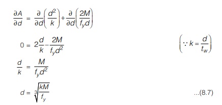
Therefore, once the depth of the girder is arrived at, general proportioning of the girder for maximum moment and shear can be done.
- For a trial girder section, k = d/tw for the web may be taken as any value ranging from 135 to 240.
However, the following provision of IS 800 : 2007 are also useful:
If d/tw < 67ε then the plate girder may designed as ordinary beam , where ε = √250/ fy
WEB THICKNESS
Initially the web thickness can be assumed as 6 mm (if painted) or 8 mm (if unpainted)
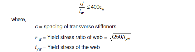
(a) Minimum web thickness based on serviceability requirement
As per Cl. 8.6.1.1 of IS 800 : 2007,
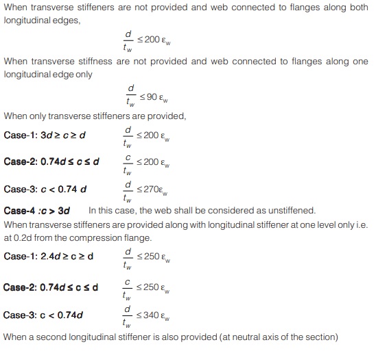
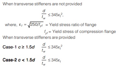
(b) Minimum web thickness based on compression flange buckling requirement
As per Cl. 8.6.1.2 of IS 800 : 2007, in order to avoid buckling of compression flange, the web thickness shall comply with the following requirements:
Thus when ε =1, the following observations can be made:
- If k = d/tw ≤ 67 then plate girder can be designed as ordinary beam without the requirement of any stiffener (except the end bearing stiffener). Such type of sections may be uneconomical.
- If k = d/tw lies between 67 and 200, it can be designed as a plate girder without intermediate stiffeners. But it must be ensured that web does not buckle in shear. For k values up to 100-110, intermediate transverse stiffeners may not be required. For larger values of k, transverse stiffeners are required for web buckling consideration.
- For k value up to 250, longitudinal stiffener is also required.
- In any case, k value should not be taken more than 345 to avoid failure of compression flange.
Intermediate transverse (vertical) stiffener:
Theoretically, intermediate transverse stiffeners are not required when the calculated shear stress in the web is less than the critical buckling shear stress of the web of the plate girder since the web will not buckle and failure of web will occur due to shear yielding of the web. Here tension field will not develop and stiffeners are not required and the web will completely be shear resistant.
- The purpose of intermediate transverse stiffener is that it increases the buckling resistance of the web.
- Before buckling of web takes place, the normal and shear stress in the web are the same irrespective of the fact that whether stiffeners are provided or not.
- If however, stiffeners are at all provided then these will remain unstressed in this case. However, due to their contact with the web (due to welding or bolts/rivets), the effect of change in the section at their line of contact (i.e. stiffener and web) and if any point load is applied to the flanges at their edges then stiffener will get stressed.
- Once the buckling of web has taken place, the transverse stiffeners become the primary load carrying members quite essential for the stability of the plate girder. Thus these transverse stiffeners must be capable enough of resisting the unbalanced vertical component of the diagonal tension as well.
The following conditions must be satisfied while proportioning a transverse stiffener:
(a) It must be sufficiently stiff so that it does not get deform considerably as the web tends to buckle.
(b) It must be strong enough to withstand the shear transmitted by the web.
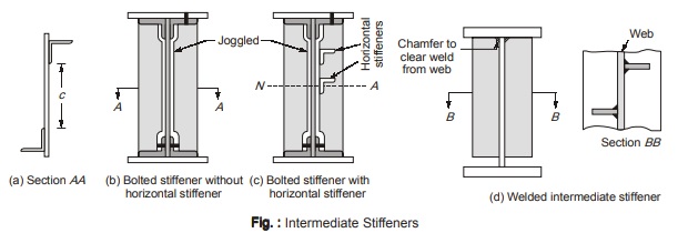
- Angle sections are provided for bolted construction of plate girders while flat sections are employed plate for welded plate girders. For bolted plate girders, angle sections are usually crimped or joggled for tight fittings as shown in figure above.
Spacing: Spacing of intermediate stiffener if provided should be as specified in Section 8.5.
Outstand of stiffener: Intermediate stiffeners are not designed as compression members but a width to thickness ratio limit must be adhered to in order to avoid local buckling. The outstand of the stiffener should comply with the provisions as specified in Section 8.11(a).
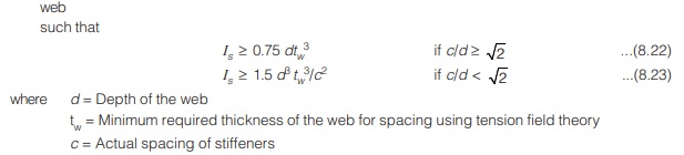
Minimum Stiffness: Transverse web stiffeners when not subjected to external loads and moments should have a moment of inertia Is
(a) about the center line of web if stiffeners are on both sides of the web and
(b) about the face of the web if stiffeners are provided alternatively i.e. single stiffener on one side of the web
Additional stiffeners will be required if these are subject to lateral loads and/or moments due to eccentricity of transverse loads w.r.t. to the web.
Buckling check:
- This check is required for intermediate transverse stiffeners only when tension field theory is used for webs.
- Stiffeners not subjected to external loads or moments should be checked for a buckling force of,
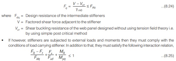
If however, Fq< Fx then (Fq – Fx) is taken as zero.
Here Fq = Stiffener force
Fdq= Design resistance of the intermediate web stiffener corresponding to buckling about an axis parallel to the web
Fx = External load or reaction on the stiffener
Fxd = Design resistance of the load carrying stiffener corresponding to buckling about an axis parallel to the web
Mq = Moment on the stiffener due to eccentrically applied load and transverse load, if any.
Myq = Yield moment capacity of the stiffener on the basis of elastic modulus about its centroidal axis parallel to the web
• Unless intermediate stiffeners are required to serve as bearing stiffeners, these intermediate stiffeners are not required to bear against the tension flange and thus their length can be kept somewhat less than the web depth (d). By doing so, the close fit fabrication problem can be dispensed with.
<< Previous | Next >>
Must Read: What is Power Electronics?
Dear Aspirants,
Your preparation for GATE, ESE, PSUs, and AE/JE is now smarter than ever — thanks to the MADE EASY YouTube channel.
This is not just a channel, but a complete strategy for success, where you get toppers strategies, PYQ–GTQ discussions, current affairs updates, and important job-related information, all delivered by the country’s best teachers and industry experts.
If you also want to stay one step ahead in the race to success, subscribe to MADE EASY on YouTube and stay connected with us on social media.
MADE EASY — where preparation happens with confidence.
MADE EASY is a well-organized institute, complete in all aspects, and provides quality guidance for both written and personality tests. MADE EASY has produced top-ranked students in ESE, GATE, and various public sector exams. The publishing team regularly writes exam-related blogs based on conversations with the faculty, helping students prepare effectively for their exams.
