Loads for Gantry Girders
In general gantry girders are laterally unsupported beam except at the column locations.
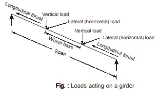
Above figure shows the various forces that act on a girder and are summarized below:
(a) Crane girder reaction acting vertically downwards.
(b) Longitudinal thrust due to starting and stopping of the crane acting in the longitudinal direction.
(c) Lateral thrust due to starting and stopping of the crab acting horizontally
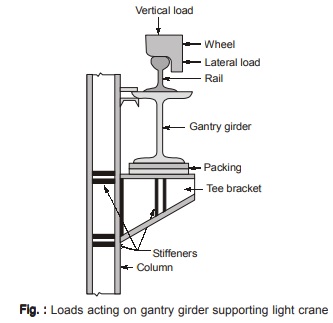
Vertical Loads
- Reaction from the crane girder comprising of self-weight of the crane, self-weight of crab and the crane capacity constitute vertical load on the gantry girder.
- The wheels attached to the crane girder transfer this vertical load to the gantry girder.
- Thus design reaction is computed from the maximum crane wheel load and it occurs when the crane is nearest to the gantry girder. Self-weight of the rail also constitutes the vertical load.
Lateral Loads / Surge Loads
Lateral loads on crane girders are caused due to the following:
(a) Sudden stopping of the crab and the load when traversing the carb girder.
(b) Crab dragging weights across the shop floor.
The lateral load is assumed to act in the plane of center of gravity of the upper flange. Now this lateral force has a lever arm that produces torque which is quite small and can be neglected safely. It is assumed that tensile flange of the gantry girder does not offer any resistance to the lateral loads.
Longitudinal Loads / Drag Loads
- Starting and stopping of the crane girders produce longitudinal forces on the gantry girders.
- This thrust is produced along the rails.
- Maximum longitudinal force acts when electrically operated crane applies brakes suddenly.
- The frictional resistance developed due to locked wheels is supplied by the rails and in turn gets distributed to the crane columns.
SPECIFICATION FOR GANTRY GIRDERS
- Gantry girders are subjected to vertical loads along with horizontal thrust/loads simultaneously.
- Thus the allowable stresses are enhanced by 10% but this enhancement in allowable stresses is not
in addition to that allowed for erection loads with or without wind or seismic forces.
Of the two horizontal forces as specified in Table 9.1 only one is able considered to act at a time along with
the vertical load.
|
Table 9.2 Vertical Deflection Limits for Gantry Girders |
||
| S.No. | Crane Type | Permissible Deflection |
|
1. 2. 3. 4. |
Manually operated cranes
Electrically operated cranes of capacity up to 500 kN Electrically operated cranes of capacity exceeding 500 kN Other moving loads like the charging cars etc. |
L/500 L/750 L/1000 L/600 |
L = Span of the gantry girder
<< Previous | Next >>
Must Read: What is Power Electronics?
Dear Aspirants,
Your preparation for GATE, ESE, PSUs, and AE/JE is now smarter than ever — thanks to the MADE EASY YouTube channel.
This is not just a channel, but a complete strategy for success, where you get toppers strategies, PYQ–GTQ discussions, current affairs updates, and important job-related information, all delivered by the country’s best teachers and industry experts.
If you also want to stay one step ahead in the race to success, subscribe to MADE EASY on YouTube and stay connected with us on social media.
MADE EASY — where preparation happens with confidence.
MADE EASY is a well-organized institute, complete in all aspects, and provides quality guidance for both written and personality tests. MADE EASY has produced top-ranked students in ESE, GATE, and various public sector exams. The publishing team regularly writes exam-related blogs based on conversations with the faculty, helping students prepare effectively for their exams.
