Beam Column Behavior
- Beam-column is the most general case as an element in a structure.
- As the flexural moment in the beam-column approaches zero, the unit will act like a column and when the axial load approaches zero, the unit will act like a beam.
- Thus all the factors that affect the behavior of beam and column individually will definitely affect the behavior of beam-column unit.
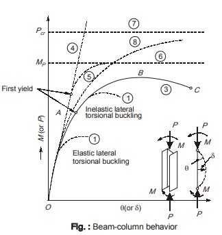
- Let there be a compact or plastic I-section beam-column. This may fail either by flexure, yielding or torsional-flexural buckling. Of course, the actual mode of failure will depend on the magnitude of axial load, its eccentricity and the slenderness ratio. Let there is no possibility of local buckling and lateral-torsional buckling. The load deflection (moment-rotation) curve OABC for such a beam column is shown in figure
below. - The curve OABC is non-linear from the beginning itself because of P-δ effect. The secondary moment induced due to P-δ effect becomes more significant as the applied end moments increase. Due to the combined
effect of primary and secondary moments, the most severely stressed fiber of the cross-section may yield as represented by point A as shown in figure. - Yielding (point A) decreases the stiffness of the member and slope of the curve after point A decreases.
- On further increasing the moments, secondary moments increase which induce plasticity into the section. Thus plastic hinge rotation gets developed at point B as shown in figure.
- On further increasing the moments beyond point B, plasticity spreads a short distance along the length of beam-column and finally the moment capacity of the section gets used up completely at point C as shown in figure..
- Slender beam-columns with open type of cross-section (like channel section) are torsionally weak and are prone to lateral torsional buckling. This lateral torsional buckling may occur either in elastic range (curve A of figure of beam-column behavior) or inelastic range (curve B of beam-column behavior) depending on the slenderness ratio.
(i) Members having large slenderness ratio will fail by elastic lateral torsional buckling.
(ii ) Members having intermediate slenderness ratio will fail by inelastic lateral torsional buckling. - Slender columns subjected to combined axial compressive load and bending may fail under different modes of instability or material failure.
Classification of Beam-column Behavior
(a) Case 1: Short column subjected to axial load and uniaxial bending about either axis or biaxial bending.
Here the failure usually occurs when plastic capacity of the section is reached.
(b) Case 2: Long column subjected to axial load and uniaxial bending about major axis. If long column is supported against lateral buckling about the minor axis, the column fails by buckling about the major axis. In case of small axial loads or if the column is not very long, a plastic hinge gets developed at the end or at the point of maximum moment.
(c) Case 3: Long column subjected to axial load and uniaxial bending about major axis. If long column is not supported against lateral buckling about the minor axis, it fails due to the combined effect of column buckling about major axis and lateral torsional buckling. In this case, column section twists as well as deflects in the major and minor planes.
(d) Case 4: Long column subjected to axial load and uniaxial bending about minor axis. If long column is supported against lateral buckling about the major axis, the column fails by buckling about the minor axis. At very low axial load, the column reaches its bending capacity about the minor axis.
(e) Case 5: Long column subjected to axial load and biaxial bending. It is a general loading case. In this case, the failure is same as that of Case 3 above but effect of minor axis buckling will be quite significant.
Thus beam-column may fail either by reaching their ultimate strength (for small axial load and short members) or by reaching their buckling strength (as governed by lateral torsional buckling or weak axis buckling).
Bolted Bracket Connection Type-I
- In this connection, the twisting moment in the bolts is in the plane of the connection as shown in figure below.
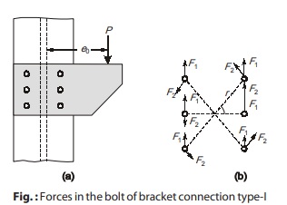
- This occurs when line of action of load is in the plane of connection and the center of gravity of the connection in elastic method or the instantaneous center in the ultimate strength method is the center of rotation. The whole bolt group is subjected to shear and torsion.
Elastic Analysis
The eccentric axial load P is made concentric along with torque T as shown above in figure (b).
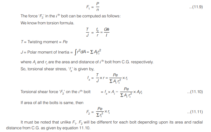
Let F1 = Force in the bolts due to direct shear, F2 = Force in the bolts due to torsion
The resultant force in each bolt (due to F1 and F2) must be less than the strength of the bolt. It is assumed that load on the joint is shared equally by all the bolts and thus force in any bolt due to direct load is,
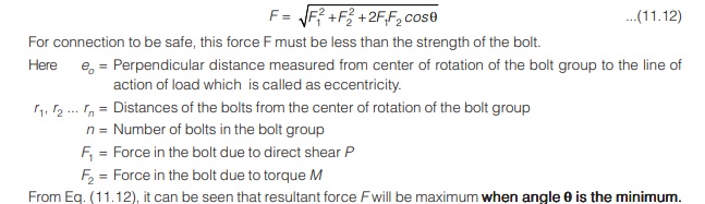
The two forces F1 and F2, act at different angles on various bolts of the connection. Let for any one such typical
bolt, the angle between the two said forces is θ. Thus the resultant F of the forces F1 and F2 on the critical bolt is,
Ultimate Analysis 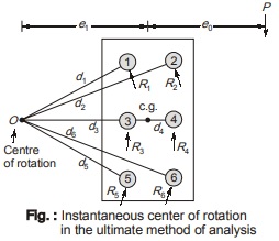
- The elastic method of analysis is quite easy to apply and gives conservative results but the assumption made in elastic analysis that applied load and bolt deformation has a linear relationship and yield stress is not exceeded are not true.
- This drawback is overcome by the ultimate method of analysis wherein the method uses experimentally determined non-linear load deformation relationship for individual bolts and thus gives quite realistic values.
The following are the assumptions made in the ultimate load method:
(a) At failure, the bolt group rotates about a point called as instantaneous center of rotation: In the ultimate method of analysis, if one of the outermost bolts starts to slip or yield, the connection does not fail at all. But the inner bolts will now take more loads under increasing load and failure occurs when all the bolts of the bolt group slip or yield. The eccentric load causes relative rotation and translation of the connected parts which is equivalent to pure rotation of the connection about a point called as instantaneous center of rotation, represented by point O situated at a distance e1 from the CG of the bolt group as shown above in figure.
(b) The deformation in each bolt is proportional to its distance from the instantaneous center of rotation and acts normal to the radius of rotation: The ultimate shear force that a bolt in a joint can resist is not the pure shear force that it can resist but it is dependent on the load deformation characteristic. The load applied to a bolt depends on its position in the joint w.r.t. instantaneous center of rotation.
(c) The capacity of the connection is said to have reached when ultimate strength of the bolt farthest from the instantaneous center is reached: The resisting force in the bolts of the connection are shown as R1, R2. . . .Rn in above figure. Each of these force is assumed to act in the direction normal to the line drawn from point O to the center of the bolt.
(d) The connected parts remain rigid: In a symmetrical connection, the instantaneous center of rotation
will lie on a horizontal line through the CG of the bolt group. This is so because the sum of the moments of the horizontal components of the force R must be zero and also the sum of the moments of the horizontal components about point O must be zero. The position of point O is found by trial and error which is a quite difficult process
Bolted Bracket Connection Type-II
- Here moment is in the plane normal to the plane of connection.
- The line of action of load does not lie in the plane of bolt group. Also the line of rotation does not passthrough C.G. of the bolt group.
The forces acting on bolts are
(i) Direct shear
(ii) Tension due to moment
Now as the direct shear force is shared equally by all the bolts thus
F = P/n
Bolts above the line of rotation are in tension and bracket section below the line of rotation will be in compression.
It is assumed that line of rotation lies at (h/7) from the bottom of bracket. where, h = Distance from bottom of bracket to top most bolt in the connection as shown in figure. Thus bolts above line of rotation will experience direct shear and tension due to moment. Bracket below the line of rotation provides necessary compression.
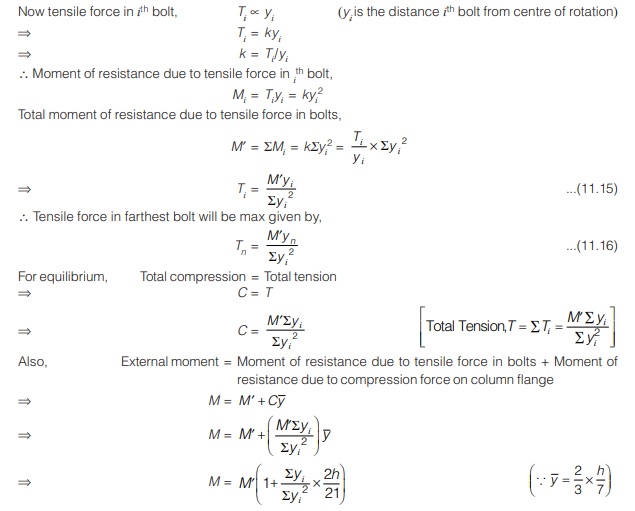

where, M = Pe0 (due to eccentric load P)
e0 = eccentricity of load P from the plane of bolt group.
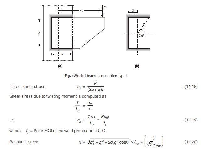
Welded Bracket Connection Type-I
Welded Bracket Connection Type-II 
- In this connection, the moment is in a plane normal to the plane of weld i.e. the CG of the weld group lies in a plane normal to the plane of line of action of load (external) and the weld group is acted upon by direct shear and bending as shown in figure below.
- Here the shear stresses and maximum bending moment occur at different locations in the joint. So combining these two stresses at a point is not possible instead these stresses are checked individually.
- Thus, when an I-section or channel sections are welded to the plate element, it is customary to assume that flange weld carries the bending moment and web weld carries the shear force. But IS code outlines a procedure to combine these two stresses. Welding can be either butt weld or the fillet weld.
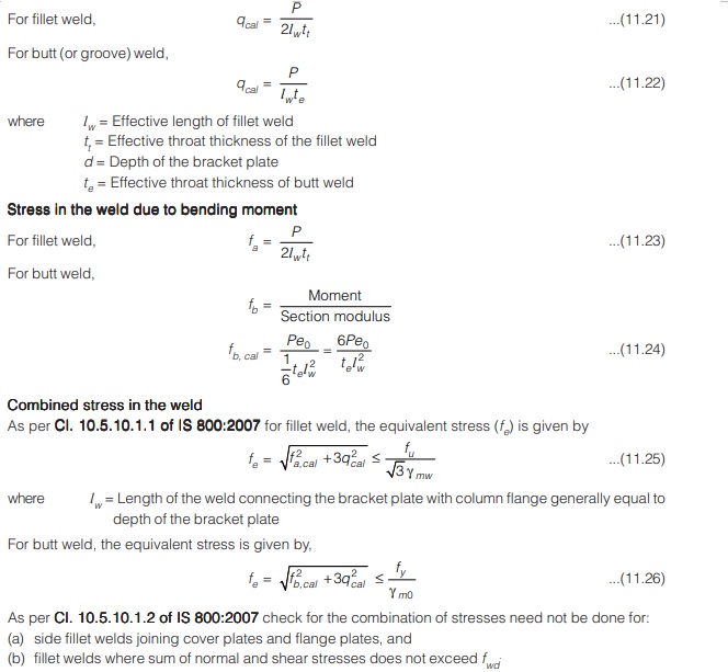
Stress in the Weld Due to Shear
The direct shear stress in the weld is given by,
q = Load (P) / Effective weld area
<< Previous | Next >>
Must Read: What is Power Electronics?
Dear Aspirants,
Your preparation for GATE, ESE, PSUs, and AE/JE is now smarter than ever — thanks to the MADE EASY YouTube channel.
This is not just a channel, but a complete strategy for success, where you get toppers strategies, PYQ–GTQ discussions, current affairs updates, and important job-related information, all delivered by the country’s best teachers and industry experts.
If you also want to stay one step ahead in the race to success, subscribe to MADE EASY on YouTube and stay connected with us on social media.
MADE EASY — where preparation happens with confidence.
MADE EASY is a well-organized institute, complete in all aspects, and provides quality guidance for both written and personality tests. MADE EASY has produced top-ranked students in ESE, GATE, and various public sector exams. The publishing team regularly writes exam-related blogs based on conversations with the faculty, helping students prepare effectively for their exams.
