Batten
- Battens are plates or any other rolled sections that are used to connect main components of the compression
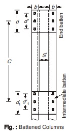 member.
 - Battens are placed opposite to each other on the two parallel faces of the compression member and must be spaced and proportioned uniformly as shown in figure.
- Number of battens should be such that the compression member is divided into at least three bays within its actual length.
- Batten may be either end batten or intermediate batten. End battens are provided at the end of battens and intermediate battens are provided in between the end battens.
- As far as strength of battened columns is considered then, it is same as that of laced columns but are not economically beneficial and are thus used sparsely.
LATERAL STABILITY OF BEAMS
- When a beam is loaded, one of the flanges of the beam comes in compression and other in tension. For economy in beam design, Iz is made considerably larger than Iy.
- Such beam sections are quite weak in bending in the plane normal to the web and thus compression flange of the beam is liable to buckle in the direction in which it is free to move i.e. in the horizontal direction. This buckling tendency increases as the ratio Iz / Iy increases. However, the bottom flange of the beam remains in tension and thus remains straight. But the bottom flange, web and the compression flange acts a unit and thus the whole section rotates as shown in figure below.
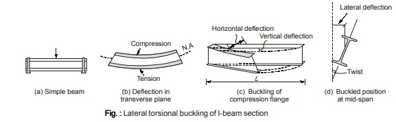
Thus it can be seen that the lateral buckling of the compression flange is also accompanied by twisting.
- When the beam deflects laterally, a torque is exerted by the applied moment about the deflected longitudinal axis causing the beam to twist. This type of instability is known as lateral torsional buckling.
- Elastic Critical Moment: It is the bending moment at which the beam fails by lateral buckling when subjected to uniform moment.
- If however, the lateral buckling of compression flange can be prevented then flexural strength of the beam can be used to its full value.
- This lateral buckling of compression flange can be prevented by any of the methods as shown in figure below and briefly described as below:
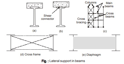
(a) By embedding the compression flange of the beam in the slab concrete which gives full lateral restraint to the beam.
(b) Shear connectors welded to the compression flange of the beam and embedded in concrete slab.
(c) Most of the non-continuous supports provide sufficient lateral support at their points of joining to the beam. When the cross beams join the main beams and are connected to compression flange then full lateral support is assumed to exist at the connections. In case cross beams are connected to tension flange of the main beam then cross bracing is done to have lateral restraint.
(d) Torsional bracing in the form of cross frames or diaphragms are used to prevent twisting.
WEB CRIPPLING
- At supports, the web of the beam may cripple due to insufficient bearing capacity as shown in figure below.
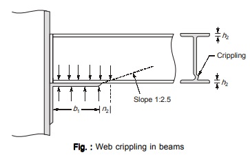
- Crippling usually occurs at the root of the section. IS 800:2007 provides an expression for computing the crippling strength of web as:
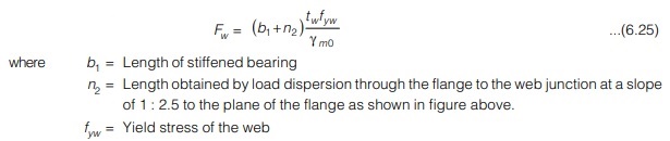
- The load transferred by bearing must not exceed web crippling strength (Fw).
- For rolled steel sections, this provision is already accounted for and thus for rolled steel sections being used as beam, there is no need to check for this failure.
- When built up sections are used as a beam then web must be checked for web crippling.
EFFECTIVE LENGTH OF LATERALLY UNSUPPORTED BEAMS
- For simply supported beams and girders of span length L where there is no lateral restraint to the compression flanges is provided but end of the beam is restrained against torsion, the effective length LT shall be as per Table 15 in IS 800:2007 and is given in Table 6.1 wherein normal loading means load is acting through shear center and destabilizing loading means load is not acting through the shear center and it creates destabilizing effect.
- In between the lateral restraints, the effective length of the segment is taken as 1.2 times the length of the segment. For cantilever beam of clear length L, effective length LLT is taken as given in Table 16 of IS 800:2007 for different support conditions and is given in Table 6.2.
<< Previous | Next >>
Must Read: What is Power Electronics?
Dear Aspirants,
Your preparation for GATE, ESE, PSUs, and AE/JE is now smarter than ever — thanks to the MADE EASY YouTube channel.
This is not just a channel, but a complete strategy for success, where you get toppers strategies, PYQ–GTQ discussions, current affairs updates, and important job-related information, all delivered by the country’s best teachers and industry experts.
If you also want to stay one step ahead in the race to success, subscribe to MADE EASY on YouTube and stay connected with us on social media.
MADE EASY — where preparation happens with confidence.
MADE EASY is a well-organized institute, complete in all aspects, and provides quality guidance for both written and personality tests. MADE EASY has produced top-ranked students in ESE, GATE, and various public sector exams. The publishing team regularly writes exam-related blogs based on conversations with the faculty, helping students prepare effectively for their exams.
